Quick Answer
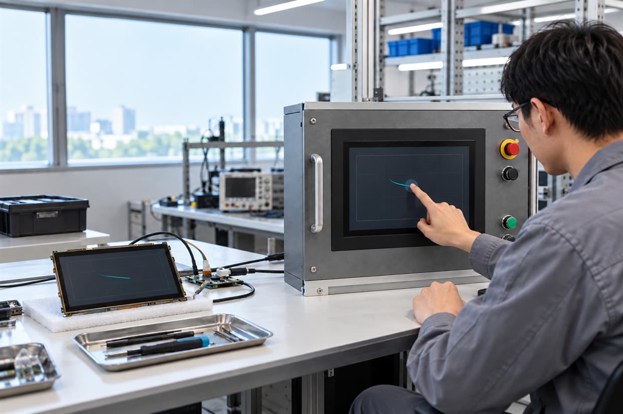
PCAP whole-system validation confirms that tapping, swiping, and edge interactions meet requirements after the touch panel and display have been installed in the device, under the actual power, grounding, mechanical, and software configuration. Even when the TP sensor or controller passes standalone tests, display noise, power conditions, and assembly differences can still affect results after integration.
- Define acceptance criteria
- Record configurations and versions
- Complete DVT and PVT in stages
A touch module passing its test does not automatically mean the complete device is ready. This article helps HMI, electronics, and mechanical teams establish validation conditions from real operating scenarios, then use consistent version and test records to narrow the investigation when problems appear after integration.
Why Can a TP That Tests Normally Fail After Installation?
PCAP determines contact position by sensing changes in capacitance. Its performance therefore depends on the surrounding electrical, environmental, material, and mechanical conditions. Settings that work with one sensor and controller combination may no longer be suitable when paired with a different LCD, power supply, or enclosure.
Debugging requires cross-functional collaboration. The touch supplier understands the sensor and controller; electronics engineers understand power and signal paths; and mechanical engineers understand spacing and assembly stress. The system integrator needs to connect this information to identify where the issue originates.
| Integration Area | Items to Confirm | Recommended Participants |
|---|---|---|
| TP | Sensor drawing, FPC, controller board, interface, and pairing settings | Touch supplier, electronics engineering |
| LCD and power | LCD part number, drive and backlight modes, power architecture, cabling, and grounding | Display supplier, electronics engineering |
| Cover glass and mechanics | Cover-glass thickness, bonding materials, spacing, bezel, mounting method, and tolerances | Mechanical engineering, bonding and assembly teams |
| Firmware and host | Firmware and parameter files, drivers, operating system, and HMI software versions | Firmware and software engineering |
| System release | Requirements, validation matrix, issue closure, and revalidation scope after changes | System integrator, quality, and manufacturing |
What Does Normal Touch Performance Mean? Start with Actual Use
The expected result for normal touch operation differs between pressing large buttons and dragging a small slider. Clarifying how the device will be used before testing determines which behaviours to observe. Otherwise, testing taps at the centre of the screen may still miss the edge interactions users care about most.
- OperationWill users operate with bare fingers or specified gloves? Are single touch, multitouch, swiping, or long presses required? Can small edge buttons be used reliably?
- EnvironmentMust the device work with water droplets present or after cleaning? Is the installation orientation the same as during testing?
- Device stateDoes touch performance remain consistent during startup, wake-from-standby, backlight adjustment, or peripheral-load switching?
- Acceptance methodIn addition to whether a target can be selected, agree on acceptable limits for coordinate deviation, missed touches, false touches, response time, and recovery after an abnormal event.
For example, operation with gloves and avoiding false touches in the presence of water are two different requirements. If users wearing gloves will touch a damp surface, the test must combine both conditions. This reflects actual needs better than merely stating glove support and water resistance in a specification.
Why Does Touch Behavior Change When the Display or Power Changes?
If an issue occurs only with a particular image, brightness level, or load, those changes are useful diagnostic clues. LCD drive conditions, backlight operation, and power conditions can affect touch signals. Even when a controller includes noise-handling functions, it must still be verified with the actual display and complete device configuration.
Start with the Image and Brightness That Reproduce the Issue
First fix the hardware and firmware, then compare operation with static patterns, dynamic images, and different backlight modes. If the issue is concentrated under one condition, retain the image, brightness setting, and touch trace. Where controller raw signals or diagnostic data are available, compare them as well to determine whether touch variation is related to the display state.
An Improvement with a Different Power Supply Is a Clue, Not the End of the Investigation
A laboratory power supply that meets the electrical specification can help compare the effect of power conditions. However, changing the power supply can also change grounding or interference-coupling paths. Verification must therefore return to the intended power supply, cable configuration, and device load. Grounding should be reviewed against the complete system design, including signal ground, enclosure, and shielding connections.
Ghost touch describes an unexpected touch event; it does not identify the failure source. If changing the power supply improves the behaviour, the next step is to identify which condition produced the difference and compare the original and corrected configurations. Do not immediately conclude that the sensor is damaged or that the power supply is defective.
What Can Change After Adding a Bezel and Completing Bonding?
A metal bezel, the gap between the sensor and LCD, cover-glass thickness, and assembly stress can all make installed conditions different from those of a bare module. If missed edge touches appear only after installation into an enclosure, comparing operation before and after assembly can help narrow the investigation.
Bonding is not only an appearance consideration. Materials and thicknesses form part of the overall stack-up. When planning temperature, humidity, or other tests for the operating environment, observe both bonding condition and touch performance. Recording material and process versions makes it possible to know what to compare when differences emerge. Optical bonding alone is not proof that electrical interference has been eliminated.
Why Should You Retest After Updating Settings on the Same Hardware?
Touch performance is not determined by hardware alone. Controller firmware, parameters, and host software are also involved. If a report states only “latest version,” it becomes difficult to determine later whether a component changed, a setting differs, or the host is processing data differently.
Keep the sample serial number, BOM, and drawing revision together with firmware, parameter file, driver, and HMI software versions. This gives old and new results a clear basis for comparison. When the LCD, power supply, FPC, or bonding material changes, retest items can be selected according to the change impact. After production begins, confirm that programmed and read-back settings match the version that passed testing.
What Do DVT and PVT Each Need to Prove?
DVT asks whether the design can meet user requirements. PVT asks whether the same result can be consistently produced using actual production materials and processes. Terminology may vary among companies, but these questions should be evaluated separately.
Step 1
Define requirements
Confirm operation, environment, and acceptance criteria.
Step 2
Record configuration
Retain samples, BOMs, drawings, and versions.
Step 3
DVT validation
Confirm design performance under required operating conditions.
Step 4
Pilot-run comparison
Check differences using actual materials and assembly.
Step 5
PVT release
Confirm that the process can reproduce results consistently.
| Validation Area | DVT Design Validation | PVT Production Validation |
|---|---|---|
| Basic operation | Validate tapping, swiping, edge operation, and multitouch under required scenarios | Confirm pilot samples and process consistency according to approved procedures |
| Display and electrical | Cross-check images, backlight, power, loads, and grounding configuration | Verify actual materials, cable configuration, and grounding assembly |
| Mechanics and bonding | Cover approved tolerances, mounting method, and applicable environmental conditions | Confirm that bonding, assembly, and inspection procedures can reproduce the design |
| Firmware and host | Validate version pairing, wake-up behaviour, and recovery from abnormal events | Verify programming, parameter read-back, traceability, and version-error prevention |
| EMC and environment | Arrange applicable tests according to device requirements and observe operation and recovery | Determine sampling and regression items based on risk and pilot-run changes |
This matrix can serve as a starting point for test discussions. Add sample quantity, conditions, pass criteria, and owners for each project, then link them to the relevant requirements and test results. If a new failure mode appears during a pilot run after DVT has passed, clarify whether the cause is design- or process-related and then confirm the effectiveness of the correction. Completing a pilot quantity alone does not demonstrate stable touch performance.
Frequently Asked Questions About PCAP Whole-System Validation
1. If a PCAP module passes standalone testing, why is whole-system validation still needed?
Module testing takes place under specific conditions. Once installed in a device, the LCD, power supply, grounding, mechanics, and host software can all affect touch performance. Tapping, swiping, and edge operation should therefore still be confirmed in the actual assembly and use scenario.
2. Does ghost touch after installation mean that the sensor is damaged?
Not necessarily. Ghost touch is an unexpected touch event and may relate to display noise, power, grounding, mechanics, or settings. Recording the image, brightness, load, and operating conditions when the issue occurs, then comparing them one by one, helps narrow the possible causes.
3. If touch works normally with a laboratory power supply, can the problem be considered solved?
Not yet. Changing the power supply can change both power conditions and grounding-coupling conditions. Improvement is a useful debugging clue. The final verification must still use the intended power supply, cabling, and device load to confirm corrected whole-system performance.
4. Is retesting required when only firmware or touch parameters are updated?
The impact should be confirmed according to the change. In addition to retesting the scenario where the original issue occurred, check interactions that may be affected. For example, after changing scan or filtering settings, reconfirm glove recognition, swipe continuity, edge operation, and response time according to device requirements.
5. Why is PVT still needed after DVT has passed?
DVT confirms whether the design meets requirements, while PVT confirms whether actual production materials, assembly processes, and firmware settings can consistently produce a product that meets specification. Design samples passing a test still need pilot-run confirmation of process and product consistency.
Planning a PCAP HMI, or facing a situation where the module works normally but becomes unstable after installation? Prepare the stack-up drawing, LCD and power information, mechanical drawings, operating scenarios, and abnormal-event records to focus the discussion on the right validation direction sooner.