Quick Answer
When ghost touches occur on a PCAP interface, first identify the conditions that trigger them before concluding that the panel has failed. Investigate three areas: conductive paths created by moisture, insufficient signal margin when gloves are worn, and system-level EMI. Establish a repeatable test baseline, change one condition at a time, and confirm the cause through reproducible testing. Any sensitivity adjustment should also be validated under real operating conditions for both false-touch control and usable touch performance.
- Start with a dry, bare-hand, low-interference baseline
- Reproduce moisture, glove and EMI conditions separately
- Validate improvements in the complete system environment
What Does Ghost Touch Look Like?
On an industrial PCAP human-machine interface, the system may register taps, swipes or multi-touch events even though the operator has not touched the screen. This behaviour is known as ghost touch. Typical field symptoms include cursor movement while idle, repeated activation in a specific area, and brief touch events when a motor starts or stops or when the backlight changes state.
With work gloves on, taps may fail to register or drag operations may be interrupted. Increasing sensitivity can improve glove operation, but may also increase false touches. Recording these symptoms separately is essential for identifying the conditions behind each one.
PCAP technology detects touch through changes in capacitance. Surface water films, conductive contamination, grounding and cable coupling, cover-glass thickness, glove material and controller parameters can all affect the touch signal. During troubleshooting, change conditions one by one and compare the results. Once the cause is confirmed, the mechanical design, cable routing or controller settings can be adjusted accordingly.
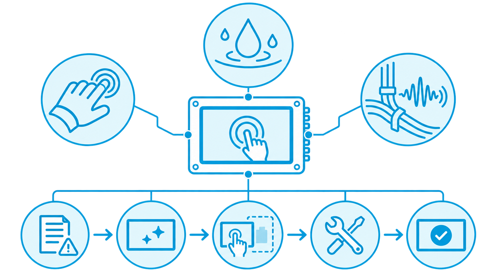
Diagnostic Principle: Establish a Baseline and Compare One Trigger at a Time
Before testing, document the equipment state, power configuration, grounding method, backlight and motor/VFD status, cable routes, firmware and controller settings, cover-glass cleanliness, and glove type. Change only one condition in each test cycle, then compare the effects of moisture, gloves and EMI against the touch-event log.
- Establish a baseline: Test with a dry cover glass, bare-hand operation and suspected loads switched off. At the same time, check whether touch events occur with no user contact.
- Reproduce each condition: Introduce moisture, change gloves or activate a suspected interference source separately. Record touch location, duration, frequency and the conditions that repeatedly trigger the issue.
- Retest after each improvement: Reconfirm performance at the baseline and under full operating conditions after every adjustment. If the initial test used a bench power supply, reconnect the actual power system and validate under full load and normal operating conditions.
Moisture and Conductive Contamination: Identify Where Liquid Remains and How It Affects the Signal
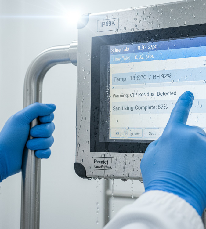
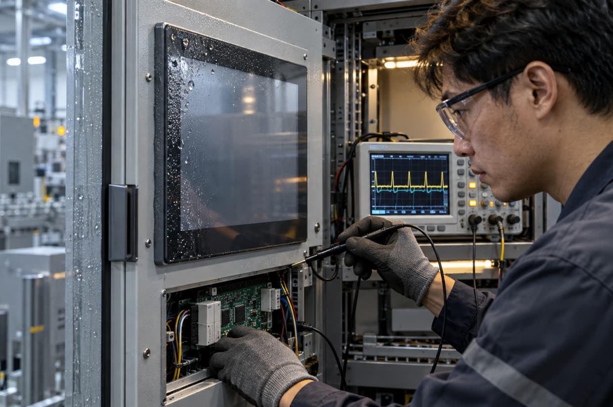
When investigating moisture-related issues, begin by observing liquid distribution across the cover-glass surface, bezel and cable-exit area. Water droplets, water films, cleaning-fluid residue, perspiration and metallic dust can all change local capacitance and affect touch interpretation. If the issue follows splashing, condensation, cleaning, or temperature changes in a humid environment, record where the liquid entered, where it remained and whether touch operation recovered after drying.
Recommended Moisture-Isolation Test
- 1. Establish a dry baselineClean and dry the cover glass, bezel and FPC exit area. Under actual power and load conditions, observe the touch log while no one is operating the interface.
- 2. Perform zoned water-drop testingWithin the protection capability of the assembly, apply small controlled water drops separately to non-operating areas, operating areas and locations near the bezel. Record the touch response in each area. Confirm the test scope and liquid volume in advance to prevent liquid from entering unprotected areas.
- 3. Dry one area at a timeDry the cover-glass surface, bezel and cable-exit area in sequence. Observe the touch response after each area is dried to determine whether the abnormal behaviour disappears with that area.
- 4. Verify mechanical improvementsBased on the test findings, review sealing, drainage, front-frame compression and cable-exit design, then confirm the improvement with a prototype. The engineering team should define test conditions and acceptance criteria for the actual application environment.
Glove-Use Validation: Test the Actual Gloves and Operating Conditions
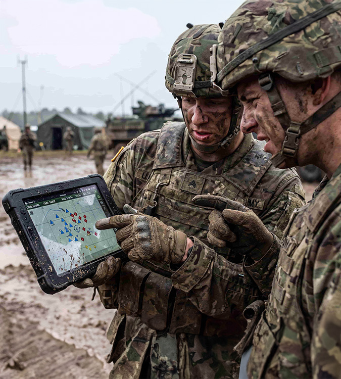
Glove material, thickness, wet or dry condition, and how closely the glove fits the finger all affect the touch signal. Non-conductive or thicker gloves may reduce capacitive coupling. Damp gloves, conductive fibres or surface contamination can also change touch behaviour. Tuning should cover the glove types used in the field and confirm performance when the operating angle and contact area change.
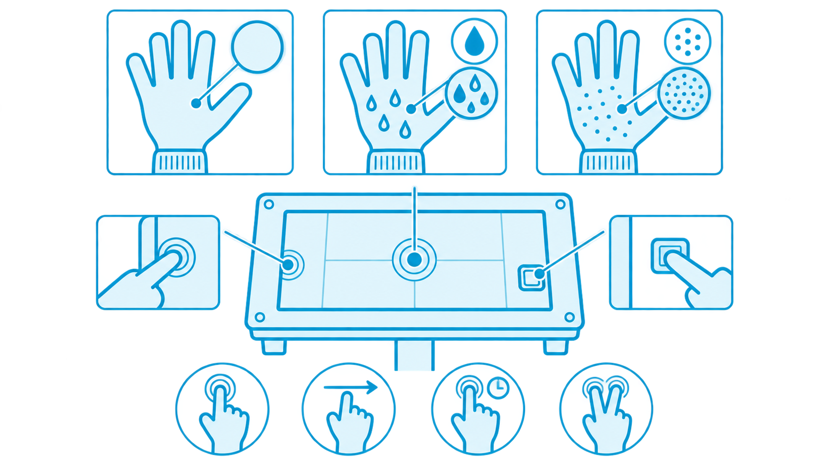
Conditions to Include in Glove Testing
- Glove type and condition: Test each specified glove individually, including dry conditions and the contamination or moisture conditions likely to occur in real use.
- Operating area and gestures: Test tapping, dragging, long presses and any required multi-finger gestures at the centre, edges and functional areas where unintended activation is more likely.
- Operator and equipment conditions: Include multiple operators and test with the actual grounding arrangement and complete equipment load.
After increasing sensitivity to improve glove operation, retest bare-hand, moisture and EMI conditions as well. Validation should confirm that operators can repeatedly complete the required tasks with the specified gloves while also recording whether false touches occur when the interface is unattended. This creates a sound basis for parameter adjustment and acceptance.
EMI: Compare the Timing of False Touches with Equipment Events
If ghost touches occur frequently during motor start-up, relay switching, backlight dimming, charger connection or disconnection, or communication activity, investigate EMI as a priority. Interference may affect touch signals through power, grounding, FPC/USB/I²C cable assemblies or mechanical coupling. First identify which equipment events correlate with false touches, then trace the source and coupling path step by step to determine where changes are needed.
EMI Isolation Process
-
1
Compare Event Timing
Align the touch log with the start and stop times of suspected loads. Repeat the operation and observe whether false touches occur at the same point in the sequence.
-
2
Compare System Configurations
While maintaining equipment safety, test first with the smallest system that retains the required functions. Reconnect external devices and loads one at a time to identify which condition introduces the issue.
-
3
Inspect Interference Paths
Check grounding continuity, shield termination and controller power quality. Also verify that touch cables are not routed in parallel with high-power or fast-switching signal conductors.
-
4
Retest After Changes
After each grounding, routing, shielding or filtering change, repeat the same equipment operating sequence and extend the observation period to confirm whether false touches recur. Where formal EMC testing is required, the EMC team should plan it against the product requirements.
Validation Process and Delivery Records
Organise test conditions, corrective actions and acceptance results into a consistent record. This helps the engineering team track the issue and provides clear confirmation criteria for subsequent delivery.
- 1. Record the symptomConfirm the conditions, location and time at which the issue occurs.
- 2. Establish a baselineConfirm touch performance with a dry surface, bare-hand operation and suspected loads switched off.
- 3. Isolate variablesIntroduce moisture, gloves and loads separately to determine whether the issue can be reproduced.
- 4. Implement improvementsUse the test results to determine the direction for changes to mechanical design, grounding, cable routing or parameters.
- 5. Validate the complete systemConfirm whether the acceptance criteria are met with actual power, complete loads and normal operating conditions.
| Stage | Key Confirmation Point | Deliverables |
|---|---|---|
| 1. Record the symptom | Under what conditions, at which location and at what time does the issue occur? | Touch-event log and site conditions |
| 2. Establish a baseline | How does touch perform with a dry surface, bare-hand operation and suspected loads switched off? | Baseline configuration and test results |
| 3. Isolate variables | Can the issue be reproduced when moisture, gloves and loads are introduced separately? | Test conditions, reproduction steps and observations |
| 4. Implement improvements | Which mechanical, grounding, cable-routing or parameter changes are supported by the test results? | Change items and rationale |
| 5. Validate the complete system | Do actual power, complete loads and operating conditions meet the acceptance criteria? | Acceptance results and open follow-up items |
Frequently Asked Questions About Industrial PCAP Ghost Touch
1. What should be recorded first if occasional PCAP false touches are difficult to reproduce in the field?
For intermittent ghost touch, first record the time, location and duration of the false touch, along with the power condition, active loads, surface moisture condition and operating method. Aligning touch records with equipment events can reveal repeating trigger conditions and support single-variable testing.
2. If the screen works normally after being dried, what should be checked next?
Recovery after drying suggests that moisture may be contributing to the trigger condition. Next, identify where liquid remains on the cover glass, bezel and cable-exit area. Controlled water-drop tests and drying one area at a time can identify the affected zone, after which the sealing and drainage design should be reviewed.
3. Glove operation has improved, but false touches now occur while the system is idle. How should the settings be adjusted?
Compare glove-operation success and idle false-touch counts before and after the sensitivity adjustment, then review controller settings one variable at a time. Each adjustment should be tested with the specified gloves, bare-hand operation, moisture conditions and the complete equipment load to find a setting that balances usable operation with false-touch control.
4. False touches appear as soon as a motor starts. How can the interference scope be narrowed down?
Repeat the motor start and stop sequence to confirm whether false touches occur at a consistent point in time, then compare results from the minimum system and the complete machine. Inspect power, grounding, touch-cable routing and shield termination in sequence. Change only one item at a time and observe whether the trigger behaviour changes.
5. Bench testing is normal, but false touches occur after installation in the machine. What additional conditions should be tested?
After full installation, the power source, grounding, cable position, mechanical coupling and loads may all differ. Use the actual power source and installed configuration for follow-up testing, activate loads one by one, and include field gloves, dry and wet conditions, and the real operating tasks to identify the condition that introduces the issue.
6. Which troubleshooting results should be passed to an EMC team for further analysis?
If false touches can be repeatedly linked to a motor, relay or other electrical event, or if the corrective action involves grounding, shielding or filtering, involve the EMC team for further analysis. Providing touch-event timing, the system configuration, reproduction steps and already-tested changes helps plan the next test. Formal EMC requirements for the product should also be included.
If your industrial HMI is experiencing touch instability related to moisture, gloves or electrical interference, begin by compiling the mechanical stack-up, controller settings, cable and grounding diagrams, and reproducible event records. Higgstec can work with your operating conditions to clarify validation criteria and help reduce repeated trial-and-error cycles.