CAPABILITY
NEWS CENTER
APPLICATIONS
SOLUTIONS
SUPPORT
TOUCHPANEL BLOG
CONTACT US
Navigating Display Anomalies: A Business Guide to Diagnosing and Preventing Touchscreen Issues
04 Feb. 2026
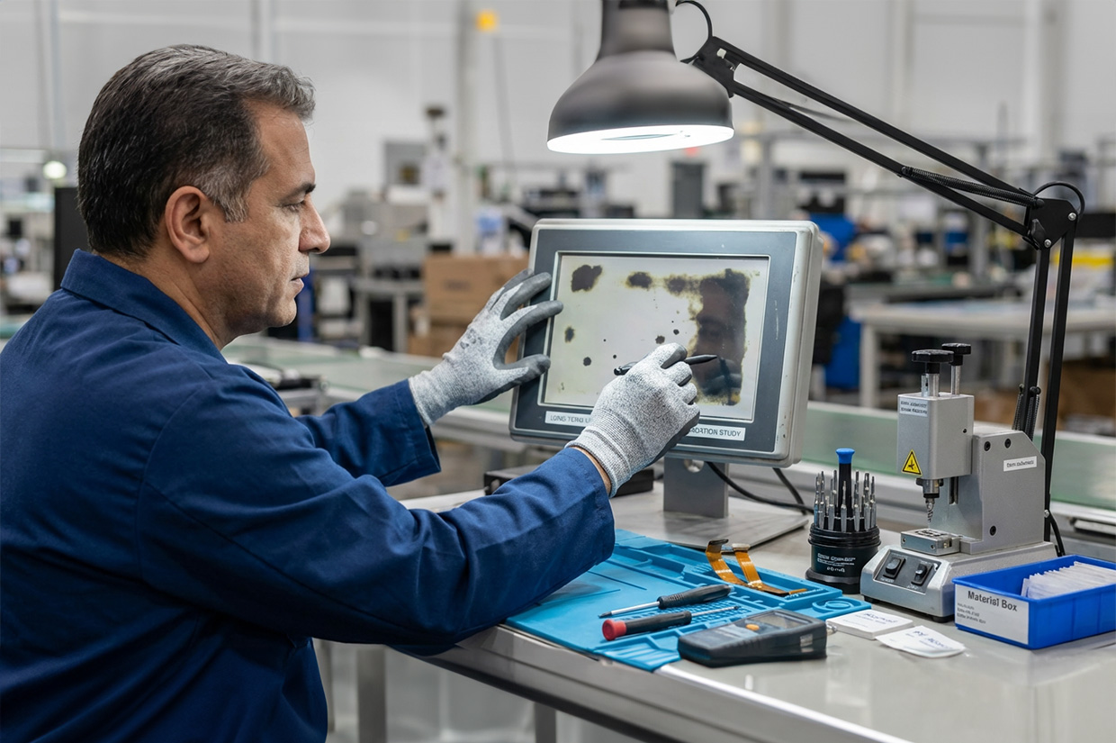
When black spots, strange yellow stains, or flickering colored lines suddenly appear on the screens of your critical equipment, what’s your first thought? To hope they disappear on their own, or to worry about costly repairs and downtime? This article provides a clear, systematic diagnostic blueprint. We break down the failure mechanisms and root causes behind common display anomalies and offer practical strategies from immediate response to long‑term prevention—a business guide to protect assets and enhance operational resilience. Let’s get straight to the point and turn problems into competitive advantage.
Before disassembly or replacement, answer three key questions to quickly determine whether the issue leans toward the system side or the display side—and decide the next steps accordingly.
Prioritize checking the video output path: OS, display driver, signal source, and GPU/mainboard image processing circuits.
Prioritize checking the display module itself: panel, backlight module, flex cable, driver IC, and lamination structure.
If yes, evaluate heat‑related factors first: suspect insufficient thermal design, component thermal drift, backlight aging, and power stability or power quality fluctuations.
If symptoms improve, focus on poor connector contact, flex cable damage, or signal interference; if symptoms are consistent and gradually worsen over time or operation, strongly suspect the display panel or structural damage.
| Checklist | Determination | System‑Side Issue | Display‑Side Issue |
|---|---|---|---|
| Screenshot test | Does a screenshot capture the anomaly? | ✓ Visible in the screenshot | ✓ Not in screenshot but visible to the eye |
| Warm‑up test | Appears only after prolonged operation? | ✓ Insufficient cooling, driver issues | ✓ Backlight aging, component drift |
| Cable test | Improves after reseating cables? | ✓ Improved → connection issue | ✓ No improvement and worsening → panel damage |
To solve problems effectively, precise diagnosis comes first. Black spots, yellowing, and lines may all look like display defects, but their root causes differ dramatically. Understanding their origins is the first—and most critical—step to choosing the right solution.
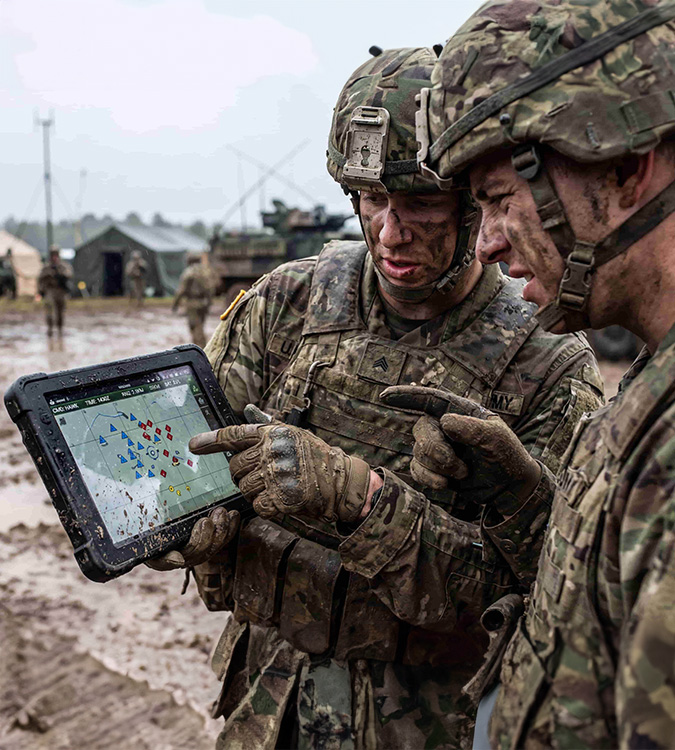
Irregular black spots, dark patches, or shadows often occur in high‑vibration or high‑stress environments such as industrial control equipment, rail transit, defense vehicles, and outdoor terminals.
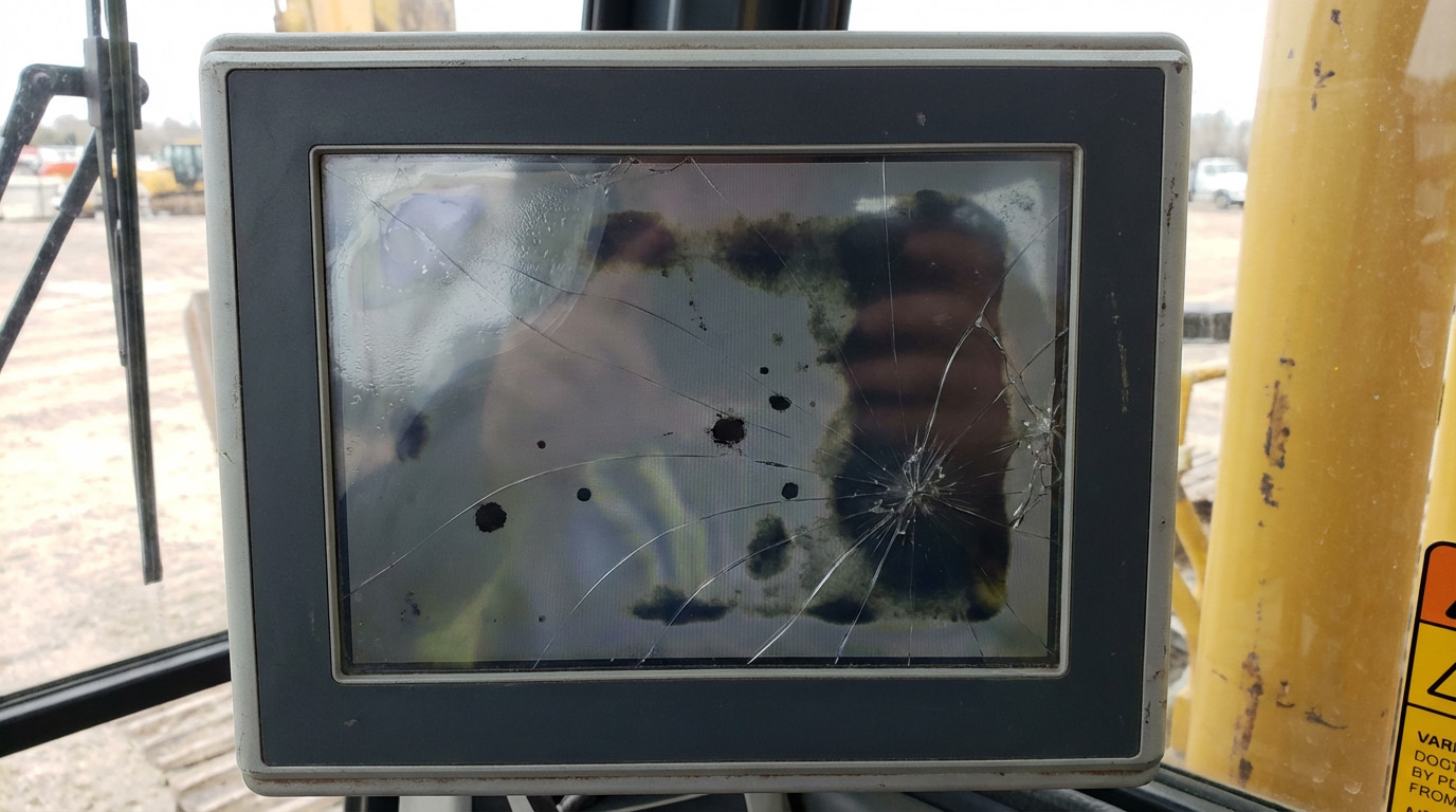
Common root causes
1. Internal stress introduced during manufacturing and assembly
Panel and module assembly involves precision lamination and fastening of multiple layers. Uneven lamination pressure, improper torque at fasteners, bezel pressure, or mismatched fixtures can create internal stress points. These stresses amplify with temperature cycling or vibration and eventually manifest as black spots.
2. Vibration, compression, and impact causing micro‑cracks and optical film damage
Long‑term vibration, impact, or external pressure can cause micro‑cracks or localized damage in the glass, structural layers, or optical films. These defects alter liquid‑crystal alignment and light transmission, reducing local luminance and forming fixed black or dark patches. Under continued stress, cracks and film damage may propagate, enlarging the affected area and degrading overall display quality.
Business impact
Beyond readability, black spots can impair precise touch operations in HMIs, leading to mis‑touches and downtime. If defects spread, repair and replacement costs can rise significantly.
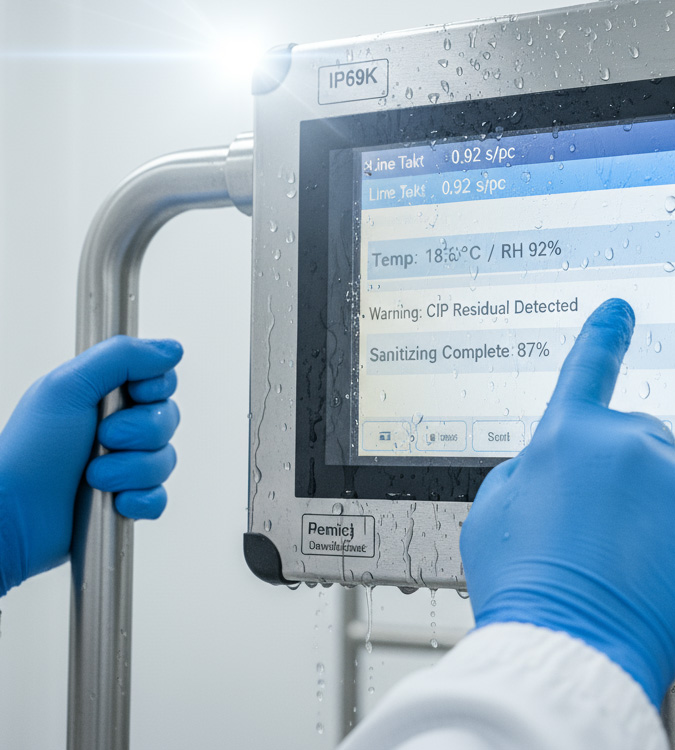
Localized yellowing, stains, or color shifts often appear near edges, heat sources, or areas with prolonged light exposure. In high‑humidity, outdoor, transportation, and medical settings, UV, high temperature/humidity, and chemical cleaning all accelerate onset.
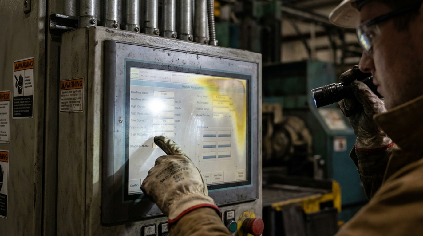
Common root causes
1. Surface coating degradation
Anti‑reflective, anti‑glare, or anti‑smudge coatings can undergo chemical changes after prolonged exposure to heat, humidity, UV, or chemicals, causing uneven transmittance and localized yellowing or color shifts.
2. Adhesives and optical films aging
Adhesives or optical films degrade under heat and UV. UV disinfection in medical settings, sun exposure outdoors, and hot, humid factory environments can lead to yellow spots and reduced color uniformity.
Business impact
Yellowing hinders color‑critical tasks—medical imaging review, inspection/QC stations, and design approvals—hurting accuracy and consistency, and potentially creating compliance risks.
Vertical or horizontal stripes, colored lines, flickering lines, or localized garbled images usually signal stability problems. In industrial equipment, the three most common causes are overheating, cable/connector issues, and electromagnetic interference.
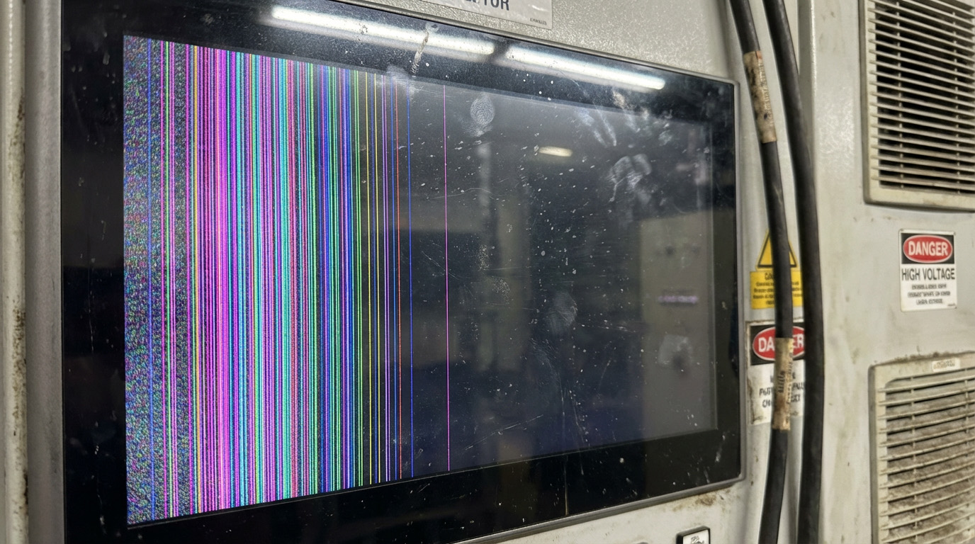
Common root causes
1. Overheating leading to unstable drive
Driver ICs and the backlight module are major heat sources. When cooling is inadequate, airflow is blocked, enclosures are sealed, or ambient temperatures are high, signal and power stability drops, causing stripes and artifacts.
2. Poor contact in flex cables and connectors
Delicate flex cables are sensitive to vibration, bending, pull, or poor strain relief, causing impedance changes or intermittent contact—often showing as intermittent lines.
3. Electromagnetic interference degrading signal integrity
Nearby inverters, motors, and high‑power devices can inject interference, especially problematic for high‑speed signals, leading to lines, flicker, or intermittent artifacts.
Business impact
Lines are rarely just image artifacts—they’re early signs of system instability. Without timely remediation, they may worsen into black screens or total failure, interrupting critical processes and causing unpredictable losses.
Comparative Table of Root Causes for the Three Major Anomalies
| Anomaly Type | Appearance | Primary Causes | Typical Scenarios | Business Impact |
|---|---|---|---|---|
| Black/Dark Spots | Irregular black spots, shadows | • Internal stress • Vibration‑induced micro‑cracks • Physical damage |
Industrial control, rail transit, defense vehicles | • Hard to read • Touch inaccuracy • Rising repair costs |
| Yellow Spots/Yellowing | Localized yellowing, color shift | • Surface coating degradation • Adhesive aging • UV exposure |
Outdoor, medical disinfection, hot and humid sites | • Color judgment errors • Consistency declines • Compliance risks |
| Stripes/Lines | Vertical/horizontal lines, flicker | • Overheating → unstable drive • Poor cable contact • EMI |
Near high‑power equipment, sealed enclosures | • System instability • Potential total failure • Process interruptions |
This workflow is designed for rapid on‑site response, cutting downtime while preserving critical evidence. It’s suitable for O&M and asset management teams to standardize.
Use photos or videos to record locations, frequency, flicker or spread, and log device temperature and run time at that moment.
The goal is to shorten fault isolation time and avoid misdiagnosis due to state changes
Clean the display surface with lint‑free cloth and screen cleaner while checking for bezel pressure, chassis deformation, and over‑tightened fasteners.
The goal is to eliminate false anomalies caused by dirt or mechanical stress
Restore display settings to defaults and check color temperature, brightness, and contrast; update firmware or display drivers if allowed.
The goal is to quickly rule out color bias or output parameter issues
Power down per safety procedures and check cable and connector retention; cross‑test with substitute cables if needed.
The goal is to eliminate intermittent lines caused by poor contact, cable fatigue, or interference
If the above steps don’t resolve the issue, it likely involves hardware such as the panel, backlight, driver ICs, or lamination structure. Compile evidence, triggering conditions, and environmental info and submit to a specialist team to quickly decide repair or replacement strategy.
Truly stable display quality comes from a holistic strategy across design, materials, process, and validation—not just post‑failure swaps. Below are four common, practical directions for OEMs/SIs, especially for cross‑region shipments to Europe, North America, and Asia.
Don’t base procurement solely on unit price; prioritize overall stability, environmental robustness, and maintainability. For oil, moisture, gloved operation, and long duty cycles, choose industrial‑grade materials, structures, and reliability designs to cut failure rates and downtime costs.
Institutionalize screen cleaning, thermal/dust management, connector inspections, and temperature/humidity/UV exposure controls. In high‑humidity markets and outdoor deployments, maintenance rigor directly determines failure rates and stability.
Ensure sufficient thermal space; avoid sealed hot enclosures. Secure cables with proper strain relief. Avoid bezel pressure during installation to reduce pressure spots and micro‑cracks.
Environmental conditions vary widely between Europe/North America and Asia: temperature/humidity, UV exposure, cleaning practices, and onsite interference. A customized module integrates materials selection, structural design, thermal, and EMI strategies so a single product platform maintains consistent reliability across markets.
Problem solved
In high‑vibration environments (industrial, defense, transportation), screens develop black spots, lines, or structural damage—compromising stability and safety.
Principle
Structural reinforcement, material selection, and damping layers reduce vibration transmitted to core panel areas, lowering stress concentrations and micro‑crack formation to preserve optical and structural integrity.
Business value
1. Improve vibration and impact resistance, reducing risk of spots, lines, and panel damage
2. Extend product life, lowering maintenance and replacement costs
3. Maintain stable displays for reliable operation under harsh vibration
Problem solved
Material aging is the root cause of yellowing and performance decay.
Principle
Choose materials by use case—e.g., UV‑resistant adhesives/films (outdoor) or antimicrobial coatings (medical).
Business value
1. Extend display life while maintaining optical and structural stability
2. Reduce performance decay and maintenance demand
3. Lower TCO and improve ROI
Problem solved
In high‑EMI or high‑frequency environments, touch panels may show stripes, flicker, or unstable touch.
Principle
Shielding designs, low‑noise signal routing, and robust grounding suppress EMI and other external interference.
Business value
1. Ensure precise touch and stable images, improving operational reliability
2. Fit for medical, industrial, and transport environments with high interference
3. Reduce maintenance and fault costs from signal issues
Together, these technologies enable professional touch panel manufacturers to deliver stable, reliable solutions for high‑spec markets like medical, defense, and food processing.
Comparison Table of the Three Key Technologies
| Technology | Problems Addressed | Principles | Business Value |
|---|---|---|---|
| AR/AG Coatings Vibration‑resistant design |
Strong reflections, glare High vibration → black spots, lines, structural damage |
• AR: optical interference to reduce reflection • AG: surface diffusion • Structural reinforcement • Damping layers absorb vibration • Reduce stress concentration and micro‑cracks |
• Readable in strong light • Anti‑smudge and easy cleaning • Lower maintenance costs • Reduce risk of spots/lines • Better vibration/impact resistance • Longer life, lower repair costs |
| Optical bonding (OB) Specialized material selection |
Secondary reflections, fogging, weak structure Material aging, yellowing, performance decay |
Seamless bonding with high‑clarity OCA • Choose materials per application • UV‑resistant adhesives/films • Antimicrobial or chemical‑resistant coatings |
• Higher contrast • Enhanced vibration resistance • Better for high humidity • UV/aging resistance • Antimicrobial (medical) • Longer life, lower TCO |
| Specialized materials EMI‑resistant design |
Material aging, performance decay EMI → stripes, flicker, touch instability |
Select materials by scenario • Shielded signal lines • Low‑noise routing • Robust grounding and EMI architecture |
• UV resistance • Antimicrobial properties • Extended service life • Stable images, precise touch • Suited to high‑EMI environments • Fewer false alarms and system issuesBreaking text |
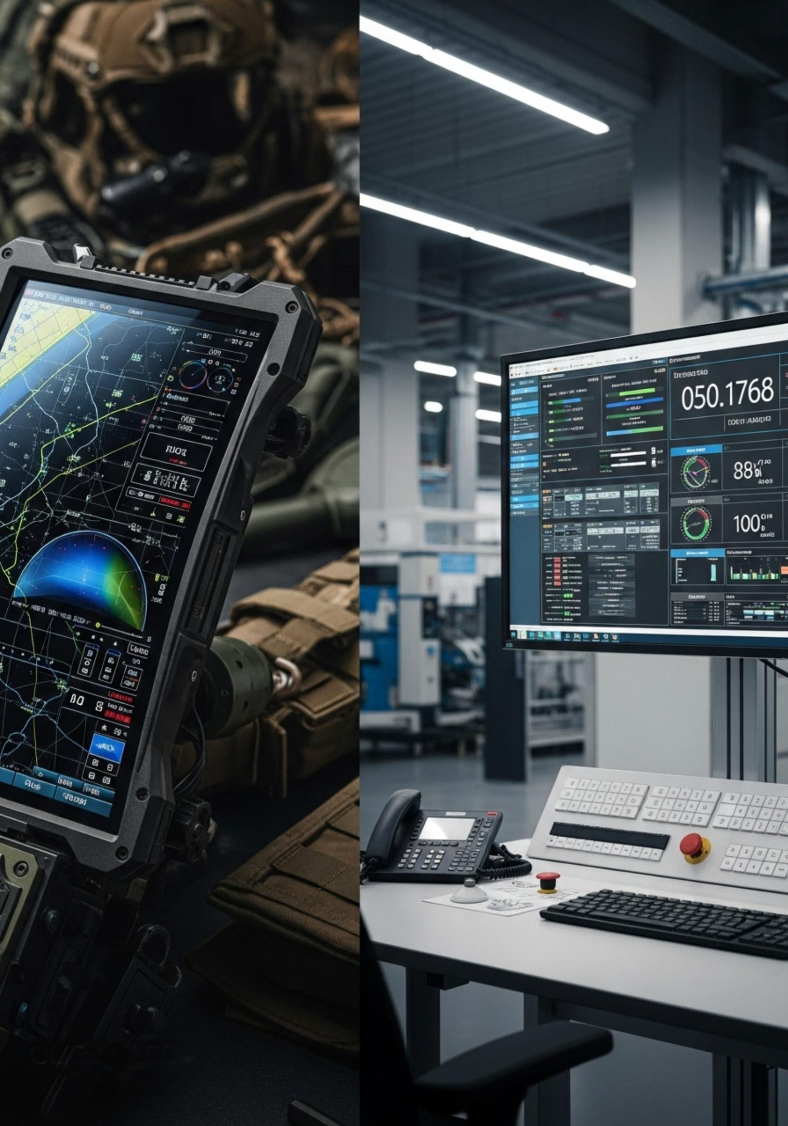
From high‑speed train cabs, to oil‑soaked food processing lines, to life‑or‑death operating rooms—each industry has unique extremes. No spec matters unless it survives the field. Here are three problem‑solving cases.
A leading rail OEM faced severe glare on the cab HMI under direct sunlight, making it hard to read speed and signals—creating a safety hazard.
Action
HIGGSTEC delivered a custom touch display integrating high‑efficiency AR coatings and optical bonding.
Result
Glare was mitigated and clarity/contrast maintained at multiple angles and lighting; optical bonding also enhanced vibration resistance for reliable long‑term operation at speed.
A large meat processor’s touchscreens were exposed to grease, blood, and high humidity, and cleaned daily with high‑pressure water. Failure rates were high, disrupting schedules.
Action
HIGGSTEC supplied an industrial touch solution with waterproof/dustproof design plus special anti‑soiling coatings for improved resistance to grease and chemicals.
Result
Stable operation in harsh conditions, easier cleaning, significantly reduced downtime and maintenance costs, and higher line throughput.
A top medical OEM developing a new surgical monitoring system needed highly responsive touch with glove support plus antimicrobial capability to meet aseptic requirements.
Action
HIGGSTEC provided a high‑precision, durable touch solution with a silver‑ion antimicrobial coating on the panel surface.
Result
Met stringent requirements for precision, durability, and safety; antimicrobial features became a market differentiator helping the customer stand out.
| Application | Challenge | Solution | Outcome |
|---|---|---|---|
| Rail Transit | Severe cab glare under sunlight | AR coating + optical bonding | • Eliminated glare • Enhanced vibration resistance • Improved operational safety |
| Food Processing | Grease, high humidity + high‑pressure wash | Water/dust proof + anti‑soiling coating | • Lower failure rates • Simplified cleaning • Higher line efficiency |
| Medical | Glove operation + aseptic requirements | High‑precision touch + antimicrobial coating | • Precision achieved • Aseptic compliance • Competitive advantage |
Black spots, yellowing, and lines appear to be display issues, but in essence reflect reliability design and process control. Only by integrating proper materials, bonding, mechanical design, thermal planning, and EMI strategies upstream can you shift risk left, maintain consistent quality across markets, and lower total cost of ownership.
If you’re planning a new product or enhancing stability of existing equipment, HIGGSTEC can provide systematic assessments and recommendations on industrial touch panels and customized display modules—covering materials, optical bonding, surface treatments, structural design, and reliability planning—so every investment becomes long‑term competitive advantage.
Black spots: structural stress, vibration‑induced micro‑cracks, or physical damage; Yellowing: material aging, heat, or UV; Lines: overheating, poor connections, or interference.
Use three questions to localize quickly
Does a screenshot capture the anomaly? If yes, troubleshoot the system; if only visible to the eye, troubleshoot the display.
Does it appear only after warm‑up or long runtime? If yes, suspect cooling or component aging.
Does reseating/replacing cables help? If yes, connector/cable issue; if it steadily worsens, panel structure likely damaged.
Black spots
Check bezel pressure and fastener torque.
Assess whether spots grow with temperature.
Trace vibration and impact history.
Yellowing
Eliminate display setting and color temperature effects.
Check if yellowing concentrates at edges, hot zones, or lit areas.
If cleaning fails, materials/coatings may have aged.
Follow these steps:
Capture images/video and environmental data.
Clean the surface and check for bezel stress.
Restore display defaults and update firmware.
Inspect cables/connectors; do substitution tests.
If unresolved, contact your supplier for expert support.
Adopt these strategies:
Use industrial‑grade materials and robust structures.
Standardize maintenance: cleaning, thermal, and inspections.
Optimize thermal design and cable strain relief to avoid pressure spots and cracks.
Use customized modules to address varying market environments.
For more technical details and customized solutions,please contact Higgstec.
Our professional team will provide you with the most precise support and service
17 Sep. 2025
01 Oct. 2025

28 Oct. 2025

12 Nov. 2025
10 Dec. 2025

06 May. 2026
Out Line Dimension , L * W * H (mm)
275.82 * 177.9* 2.1 mm
Out Line Dimension , L * W * H (mm)
291.92 * 194.00 * 2.23 mm
Out Line Dimension , L * W * H (mm)
278.3 * 216.8 * 11.13 mm
EXPLORE PRODUCTS
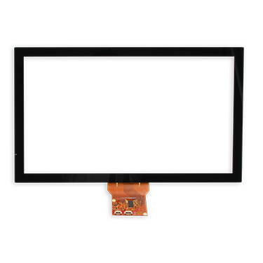
Higgstec's projected capacitive touch panels deliver smooth and stable touch performance. Additionally, with excellent electromagnetic compatibility, water resistance, sunlight readability, and other advanced specifications, they are ideal for use in various demanding environments, including industrial, rugged, medical, automotive, and marine industries.
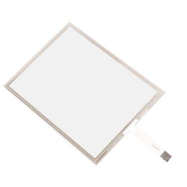
Higgstec's 5-wire resistive touch panels offer exceptional reliability and outstanding linear performance using a unique high-temperature manufacturing process. Built on standard 5-wire resistive technology, we also provide customized touch solutions tailored to meet the specific needs of our clients. These highly specialized products are designed to fulfill the requirements of diverse application scenarios, achieving optimal performance.
Integrating 5-wire resistive and projected capacitive touch panels, Higgstec extends its commitment to product quality and technological innovation to touch display modules. To meet the diverse specifications required in various industrial control fields, we provide tailored touch solutions to help clients enhance the added value of their products.